uart
In that section we are going to briefly explain how the UART IP works and how to use it in our project. For complete information about the UART IP and how its implemented, please refer to the UART Tile Project documentation.
UART, or Universal Asynchronous Receiver-Transmitter, is a communication protocol commonly used to transmit and receive data between electronic devices. It enables the serial transmission of data, allowing devices to communicate over a pair of wires. UART operates asynchronously, meaning there is no separate clock signal; instead, both the transmitting and receiving devices agree on a specific baud rate to synchronize their communication. This makes UART a flexible and widely adopted standard for serial communication in various applications, such as connecting devices like microcontrollers, sensors, and other peripherals.
We use UART to communicate with the FPGA. It helps us read data from the FPGA, like what's in its registers, debugging and more. We can also write data to the cores placed on the FPGA, such as initializing instruction and data memory. The write ability allows us to load programs to the FPGA and run them without creating
*.miffiles that represents instruction and data memory. Such process allows us to compile the design only once and then load different programs to the FPGA without the need to recompile the design.
How to use the UART IP in our project
UART interface
We communicate with UART using software interface. The interface is just a piece of code running on a Host device. The interface on one side interacts with a user by a friendly Py-Terminal and communicates with the Device via USB serial transfers.
To run the interface please install the following packages:
pip install serialpip install pySerialnote: if you have any problems installing the packages using
gitBashthen you can install them inwindows power shell. To openwindows power shelljust typewindows power shellin the search bar and click on the first result. Then you can install the packages using the same commands as above.To run the interface, go to
fpga_mafia\lotr_orig\pyterminal\srcfolder and typepython ./uart_term.py. This will open the terminal.Choose the communication port. In our example we choose COM3 (you may have other available ports instead ).
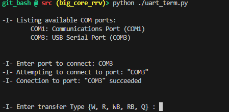
important:to make the following command works you should have the FPGA connected to the computer and to the UART. Since it may not be the case than now you may focus only on the interface options instead of the implementation. We will explain it on a real example here
-W write chosen single word to the device at a specific address.
-R read a single word from the device at a specific address.
-WB write a burst of words from a file on the host to the device starting at a specific address.
-RB read a burst of words from the device starting at a specific address to a file on the host. You can choose the transfer size.
-Q quit the terminal.
UART cable
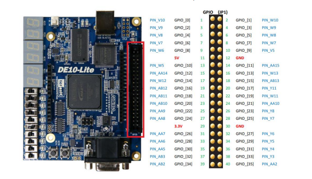
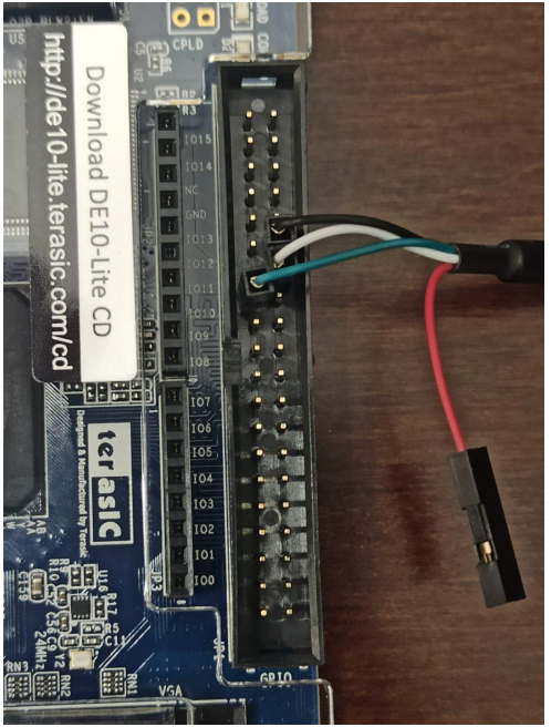
The connection to the FPGA board is done using a USB to TTL converter cable. One side is connected to the computer and the other side is connected to the FPGA GPIO pins.
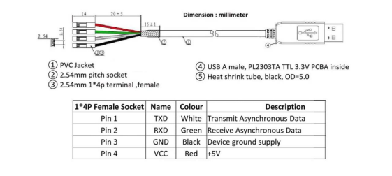
| Source | Destination | Comment |
|---|---|---|
| White(TXD) | PIN_AA15 | |
| Green(RXD) | PIN_AA14 | |
| Black(GND) | GND | |
| Red(VCC) | floating |
note: In case you have USB to TTL converter with 6 pins than use the following table:
- GND is black
- VCC is red
- TXD is orange
- RXD is yellow
Generally speaking we finished the explanations we need to use the UART. We know that the explanations here are very general. Do not worry if you do not understand everything here. We will explain it in details in real example. Just remember what each option means in the sw interface and how to connect the UART cable to the FPGA.