vga
Memory mapped I/O approach to access the VGA
Memory-mapped I/O (MMIO) is a technique where hardware devices communicate with the CPU via the same address space as the memory. This means that the memory and the I/O devices share the same address space. The CPU can read and write to specific memory addresses, and the hardware device will respond to these commands. This is a very simple and efficient way to communicate with hardware devices. each device has a specific address range in the memory.
In our project we divide the memory into 4 parts:1,2
The first part is the instruction memory, it hold the instructions of the program.
The second part is the data memory, it hold the data of the program, static data and dynamic data as defined in the linker script.
The third part is the CR_MEM which hold some control registers to communicate with the FPGA.
The fourth part is the VGA memory which hold the data to be displayed on the screen.

VGA_MEM is the memory region that responsible for communicating with the screen. Any writing to a certain area in this memory region will be reflected to the screen and in addition to that the processor can read the status of a certain pixel assuming that the software is interested in it. There is an option for this memory area to be initialized to zero by the software that run on the processor if it so wishes. The memory size is control by the parameters inside
package fileof a specific core. The access to VGA_MEM is a dual-port access because both the processor and the VGA controller can access this memory area together. The processor accesses VGA_MEM in the Memory stage. The driver that pulls the information from this memory region to the screen is the VGA Controller. In the simulation we used behavioral memory, and on the FPGA, we used the on-die FPGA memory (as same as I_MEM and D_MEM). All the memory regions that have been described so far are wrapped by mem_wrap so that at the level of this component the address is checked, and the reference is made to the relevant memory space. In relation to VGA_MEM, this memory component is wrapped by the VGA Controller and the VGA Controller is a component of mem_wrap. That is, every request to the memory area of the VGA goes through the processor, passes through the mem_wrap to the VGA Controller and then reaches the memory area of the VGA.
VGA controller and protocol specification
Important Note : Before reading the following information, you may refer to the following video and also the following link to get a better understanding of how the VGA works. 4. Its not that necessary to understand the following information, but it will help you to understand the VGA controller and the protocol specification.
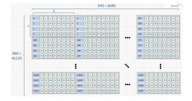
You can skip the technical details and go directly to the Implementation of VGA in our project section. For any question, please contact us.The resolution of our target screen is 640×480. There are 640 vertical bits lines and 480 horizontal bits lines. Overall, the screen contains 80×480 = 38,400 bytes, and if we take into account that the size of a word is 4 bytes, the screen contains 9600 words. Each pixel on the screen is represented by a single bit, as a result, the total number of pixels is 640×480 = 307,200 pixels. The VGA support 12 bit RGB3, but we decided that having such a large amount of memory was a waste. So, we implemented a monochromatic screen, which each pixel is either on or off.
The refresh rate of the screen is 60Hz, which means that the screen shows 60 frames(pictures) per second. Therefore the frequency of updating each pixel must be approximately 25.2Mhz(will be explained soon). In our design we will choose 25Mhz because of technical issues involving of generating 25.2Mhz
Horizontal Synchronization
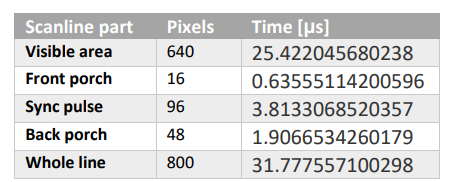
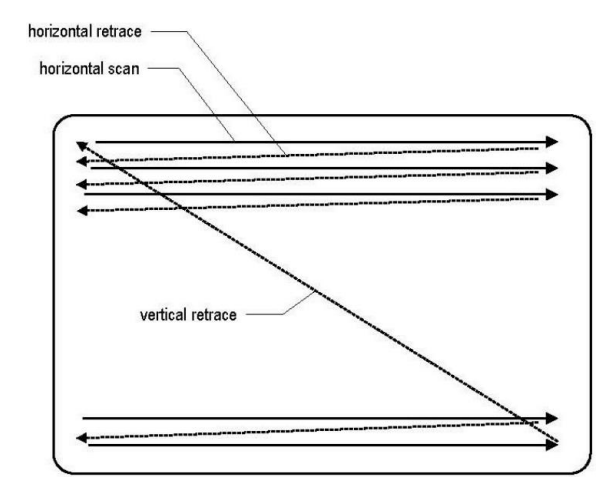
The following diagram shows the wave diagram of the horizontal synchronization signal. We will look at the hsync (horizontal synchronization) signal and how it relates to how the electron beam of the CRT monitor traverses across the CRT monitor. In the Figure we can see a CRT monitor with a black border, and the reason is because older CRT monitors did have that black border and it is part of the scanning pattern that we do. That is, we do pass the electron beam across the black border too, however we don't show any pixels over there. The hsync signal is a periodic digital signal that goes between zero and one logic. Based on the value of that signal the CRT monitor generates a sawtooth signal which moves the electron beam across the screen. The period of hsync signal is between 0 all the way to 799, which is 800. Suppose we start at the point marked 0 in the wave diagram of the hsync signal as shown in the figure, in principle we can start at any point we want because the signal is periodic. Point 0 is the start of the screen, this point located in the visible portion of the screen, not the border. We set the hsync signal to 1 all the way to 639 which means the electron beam will travels across the CRT monitor from left to right. We can observe that the sawtooth signal in this section is going all the way up, but it didn't finish though. What is happens next is that the electron beam goes through the right border (front porch) for exactly 16 clock cycles (not the system clock cycle). Then, the horizontal line must go backwards for 96 clock cycles, this is what we call the retrace and the sawtooth signal in this section is going all the way down to zero. In the final stage, relative to the point where we started (0) and because the signal is periodic the electron beam goes through the left border (back porch) for exactly 48 clock cycles. Realization of the hsync signal is basically by a simple counter which goes from 0 to 799 (modulo 800).
Horizontal synchronization signal
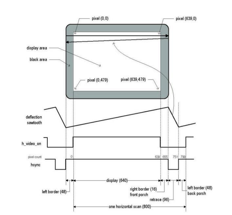
Horizontal timing
Vertical Synchronization
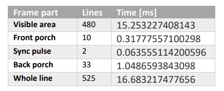
The following diagram shows the wave diagram of the vertical synchronization signal. Now, we will look at the vsync (vertical synchronization) signal and how it relates to how the electron beam of the CRT monitor traverses across the CRT monitor. The horizontal synchronization signal allowed us to move the electron beam or the scanning of the pixels from left to right, so we need another signal which goes from top to bottom, this is where the vertical synchronization signal comes into play. We want to go from top to bottom in 1/60 seconds because we have a refresh rate of 60Hz. vsync signal is very similar to hsync signal so the vsync signal is also a periodic digital signal that goes between zero and one logic. Suppose we start at the point marked 0 in the wave diagram of the vsync signal in Figure 12, here also we can start at any point we want because the signal is periodic. Point 0 is the start of the screen, this point located in the visible portion of the screen, not the border. We set the vsync signal to 1 all the way to 479 which means the electron beam will travers across the CRT monitor from top to bottom. What is happens next is that the electron beam goes through the bottom border (front porch) for exactly 10 clock cycles (not the system clock cycle). Then, the vertical line must go backwards for 2 clock cycles, this is the retrace. In the final stage, relative to the point where we started (0) and because the signal is periodic the electron beam goes through the top border (back porch) for exactly 33 clock cycles. Realization of the vsync signal is also basically by a simple counter which goes from 0 to 524 (modulo 525)
Vertical synchronization signal
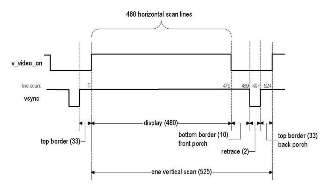
Vertical timing
Complete VGA screen scan picture
- explanation of the 25.2Mhz frequency: we need to update 60 times 800x525 pixels per second. So, the frequency of updating each pixel must be approximately 25.2Mhz.
Implementation of VGA in our project
we divide VGA into 3 files
big_core_vga_sync_gen.sv(core name can be changed depending on the core). This file is responsible for generating the hsync and vsync signals and the counters that count the pixels.big_core_vga_ctrl.sv(core name can be changed depending on the core). This file is responsible for reading and writing the pixels from and to the VGA_MEM, creating the RGB signals and 25Mhz clock signal. Each character represented in a rectangular (see the following sections) instead of turning on each picture at every line separably. We make it because its easier to represent characters in that way considering some technical limitations in our project. If you feel confused now, please let us now and we will explain it in more details.vga_mem.svis the memory component of VGA_MEM.
VGA modules hierarchy

character representation
We mentioned rectangular in the previous sections, now we will try to explain it in more details.
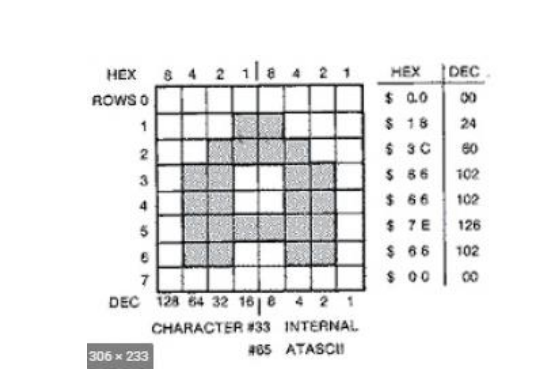
- Each character represented in 8x8 matrix. The matrix is 64 bits. so, each character is represented by 64 bits. We can see from the following figure that we can show 80 characters in each line and 60 characters in each column. So, the total number of characters that we can show on the screen is 80x60 = 4800 characters.
- Lets understand how to represent the character
A
We look at each row and each "on" pixel considered as 1 and each "off" pixel (white) considered as 0. So, the the first row is 0x00000000, the second row is 0x00011000, the third row is 0x00111100 and so on... - We divide the matrix into first 4 rows (TOP) and the last 4 rows (BOTTOM).
- Than, we represent the letter
Aas two parameters representing consecutive 4 top rows and 4 bottom rows in hexadecimal format in/app/graphic_vga.hfile.
#define A_TOP        0x663C1800
#define A_BOTTOM     0x00667E66
- You can see the full list of characters in
/app/graphic_vga.hfile ordered by ASCII code.
/* ASCII tables */
unsigned int ASCII_TOP[97]   = {0,0,0,0,0,0,0,0,0,0,0,0,0,0,0,0,0,0,0,0,0,0,0,0,0,0,0,0,0,0,0,0,0,SPACE_TOP,
                                0,0,0,0,0,0,0,0,0,0,COMMA_TOP,0,POINT_TOP,0,ZERO_TOP,ONE_TOP,TWO_TOP,
                                THREE_TOP,FOUR_TOP,FIVE_TOP,SIX_TOP,SEVEN_TOP,EIGHT_TOP,NINE_TOP,0,0,0,0,0,0,0,A_TOP,
                                B_TOP,C_TOP,D_TOP,E_TOP,F_TOP,G_TOP,H_TOP,I_TOP,J_TOP,K_TOP,L_TOP,M_TOP,
                                N_TOP,O_TOP,P_TOP,Q_TOP,R_TOP,S_TOP,T_TOP,U_TOP,V_TOP,W_TOP,X_TOP,Y_TOP,Z_TOP};
unsigned int ASCII_BOTTOM[97] = {0,0,0,0,0,0,0,0,0,0,0,0,0,0,0,0,0,0,0,0,0,0,0,0,0,0,0,0,0,0,0,0,0,
                                SPACE_BOTTOM,0,0,0,0,0,0,0,0,0,0,COMMA_BOTTOM,0,POINT_BOTTOM,0,ZERO_BOTTOM,
                                ONE_BOTTOM,TWO_BOTTOM,THREE_BOTTOM,FOUR_BOTTOM,FIVE_BOTTOM,SIX_BOTTOM,
                                SEVEN_BOTTOM,EIGHT_BOTTOM,NINE_BOTTOM,0,0,0,0,0,0,0,A_BOTTOM,B_BOTTOM,C_BOTTOM,D_BOTTOM,
                                E_BOTTOM,F_BOTTOM,G_BOTTOM,H_BOTTOM,I_BOTTOM,J_BOTTOM,K_BOTTOM,L_BOTTOM,
                                M_BOTTOM,N_BOTTOM,O_BOTTOM,P_BOTTOM,Q_BOTTOM,R_BOTTOM,S_BOTTOM,T_BOTTOM,
                                U_BOTTOM,V_BOTTOM,W_BOTTOM,X_BOTTOM,Y_BOTTOM,Z_BOTTOM};
Running simple vga test
- We will run it on
big_corecore. You can run it on any core that have VGA support. - Open or add the following test to your core
/verif/big_core/tests/alive_vga.c.
#include "big_core_defines.h"
#include "graphic_vga.h"

int main()  {

    rvc_printf("HELLO_WORLD");
    rvc_printf("GOOD DAY");

    int num = 7;
    rvc_print_int(num);

    return 0;

}  // main()
Please make sure to add
print_vga_screen taskto print the screen.
You can use the/verif/big_core/tb/big_core_vga_tb.svtest as a template. Do not forget to change the link to new TB in/verif/big_core/tb/big_core_verif_list.ffile.run
/.build -dut big_core -test alive_vga -app -sim -gui.You should see the output in
/target/big_core/test/alive_vga/screen.logfile.The content of that file will be:

1 Please note that the size and addresses of the memory regions can be changed. The current values are defined in package files of the specific core.
2 CR_MEM and VGA_MEM are not defined in all the cores.
3 When implementing the VGA controller on FPGA, please refer to its manual to see the exact RGB format cause some may have 8 bits resolution instead of 12.
4 This link is not directly related to our project, but it is a good video to understand how the VGA works and the system verilog code.