mod3_cnt

In that example we will design basic mod3 counter. The output will be a 7 segment display
| Signal Name | description |
|---|---|
| clk | 50Mhz fpga clk |
| rst | reset push button |
| seg | 7 segment display |
| up/down | cnt sw direction ctrl |
- We will implement the rst (reset) button using a push button
- We will implement the up/down button using a switch
- If up/down is 1 the counter will count up :
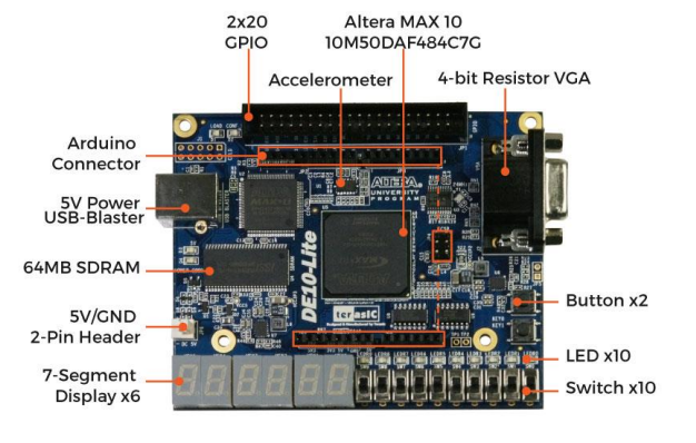
0,1,2,3,0,1,2,3,0,1,2,3...and if up/down is 0 the counter will count down :3,2,1,0,3,2,1,0,3,2,1,0... - Save your time and always read the de10_lite manual to understand the pins of the fpga. For example the push button is low active, so when you press the button the signal is 0 and when you release the button the signal is 1. By the way, thats the reason we implemented reset as active low (
!rst). The seven segment display is common anode, so you have to drive the cathodes of the display to 0 in order to light up a segment. - The push buttons are the
Buttonx2in the next figure.
lets start
- Never, Never, Never start a design without testing it with simulation. You will save a lot of time if you test your design with simulation before you implement it on the fpga.
Simulation using Modelsim
- Create file named
counter.svandcounter_tb.sv. Create file namedtest_list.fand add your files. - Create directory named
work. - For deeper explanation click here
// counter.sv file
`timescale 1ns / 1ps

`define zero  7'b1000000
`define one   7'b1111001
`define two   7'b0100100
`define three 7'b0110000

typedef enum logic [1:0] {
    Zero,
    One,
    Two,
    Three
} states;


module counter(
    input logic        clk,
    input logic        rst,
    input logic        up_down,
    output logic [6:0] seg
  );

    states ps_state, next_state;

    integer counter = 0;
    // 1 sec counter must count until 49999999.
    // de10_lite clk is 50Mhz
    always_ff@(posedge clk) begin
        if(!rst)
            counter <= 0;
        else if(counter == 49999999)
            counter <= 0;
        else
            counter <= counter + 1;
    end


    //state register
    always_ff@(posedge clk) begin
        if(!rst)
            ps_state <= Zero;
        else
            ps_state <= next_state;
    end

    // next state logic
    always_comb begin
        next_state = ps_state;
        case(ps_state)
            Zero: begin
                if(up_down && counter == 49999999)
                    next_state = One;
                else if (!up_down && counter == 49999999)
                    next_state = Three;
            end
            One: begin
                if(up_down && counter == 49999999)
                    next_state = Two;
                else if (!up_down && counter == 49999999)
                    next_state = Zero;
            end
            Two: begin
                if(up_down && counter == 49999999)
                    next_state = Three;
                else if (!up_down && counter == 49999999)
                    next_state = One;
            end
            Three: begin
                if(up_down && counter == 49999999)
                    next_state = Zero;
                else if (!up_down && counter == 49999999)
                    next_state = Two;
            end
        endcase
    end

    // output logic
    assign seg = (ps_state == Zero) ? `zero : (ps_state == One) ? `one : (ps_state == Two) ? `two : (ps_state == Three) ? `three : 7'b1111111;

endmodule
notes:
- The clock of our fpga is 50Mhz. In order to change the display every second we need to count until 50 million and than change the display value. Thats the reason we use the counter variable.
- In the simulation its recommended to set the counter variable to smaller number, for example 3. That way you can see the changes faster. In our simulation we will set it to 3.
// counter_tb.sv file
`timescale 1ns / 1ps

module counter_tb();

    localparam DELAY = 10;

    logic clk;
    logic rst;
    logic up_down;
    logic [6:0] seg;

    always #DELAY clk = !clk;

    counter counter (
    .clk(clk),
    .rst(rst),
    .up_down(up_down),
    .seg(seg)
  );

    initial begin
        clk     = 1'b0;
        rst     = 1'b0;
        up_down = 1'b1;
        #(4*DELAY);

        rst =  1'b1;
        #(50*DELAY);

        up_down = 1'b0;
        #(50*DELAY);

        up_down = 1'b1;
        #(50*DELAY);

        $finish();

    end
endmodule
Compilation
Compile the design in the terminal using the following command:
vlog.exe -f test_list.f
- Do not forget that we are using Modelsim and not Quartus. We will soon return to Quartus
Simulation using gui
- Open Modelsim using the following command:
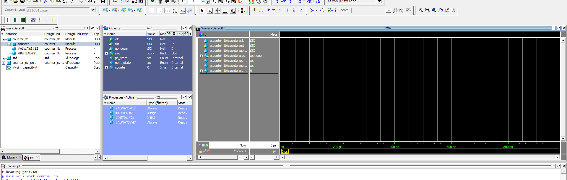
vsim.exe -gui work.counter_tb
Drag the counter signals to the wave window. You can also use the following command:
Press the marked button to run the simulation. Fit the waves using zoom in/out buttons.
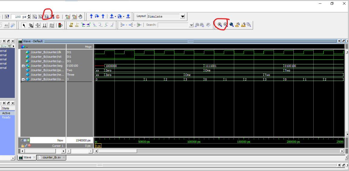
Observe the changes of the signals. Note that the counter is counting up and down every 4 clock cycles cause we set the counter to be 3 (0, 1, 2, 3).
Quartus
After the design validation we can implement the design on the fpga.
- Open Quartus and open the project as we created in the
basic_example. - Change the counter variable to 49999999.
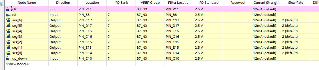
- Compile the design and open pin assignment.
- Use the de10_lite manual to assign the pins.
- Program the device and observe the changes on the 7 segment display.