rf
Register File
- Register file is a collection of registers. In RV32I there are 32 registers and in RV32E there are 16 registers, Each register is 32 bits wide. Number of registers can be changed by changing the
RF_NUM_MSBparameter. - The register file has two read ports and one write port.
- Register file is a part of second stage of the pipeline named
CYCLE Q101H.
Instantiation of register file in mini_core.sv
mini_core_rf
#( .RF_NUM_MSB(RF_NUM_MSB) )
mini_core_rf (
  .Clock            (Clock),          // input
  .Rst              (Rst),            // input
  .Ctrl             (CtrlRf),         // input
  .ReadyQ102H       (ReadyQ102H),     // input
  // input data path
  .ImmediateQ101H   (ImmediateQ101H), // input
  .PcQ101H          (PcQ101H),        // input
  .RegWrDataQ104H   (RegWrDataQ104H), // input
  // output data path
  .PcQ102H          (PcQ102H),        // output
  .ImmediateQ102H   (ImmediateQ102H), // output
  .RegRdData1Q102H  (RegRdData1Q102H),// output
  .RegRdData2Q102H  (RegRdData2Q102H) // output
);
Signal description
- CtrlRf: This is a part of
typedef struct packed named t_ctrl_rf(see mini_core_pkg.vh file) variable. - ImmediateQ101H: Immediate value of instruction.
- ImmediateQ102H: Immediate value of instruction passed to the next stage of pipeline through ID/EX register.
- PcQ101H: Program counter value of instruction from previous stage of pipeline (Q100H).
- PcQ102H: Program counter value of instruction passed to the next stage of pipeline through ID/EX register.
- RegRdData1Q102H: Register read data 1 value of instruction passed to the next stage of pipeline through ID/EX register.
- RegRdData2Q102H: Register read data 2 value of instruction passed to the next stage of pipeline through ID/EX register.
Register file module mini_core_rf.sv
`include "macros.sv"

module mini_core_rf
import common_pkg::*;
#(parameter RF_NUM_MSB)
(
    input logic Clock,
    input logic Rst,
    // input control path
    input var t_ctrl_rf Ctrl,
    // input data path
    input  logic        ReadyQ102H,
    input  logic [31:0] PcQ101H,
    input  logic [31:0] ImmediateQ101H,
    input  logic [31:0] RegWrDataQ104H,
    // output data path
    output logic [31:0] PcQ102H,
    output logic [31:0] ImmediateQ102H,
    output logic [31:0] RegRdData1Q102H,
    output logic [31:0] RegRdData2Q102H
);


logic [RF_NUM_MSB:1][31:0]  Register;
logic                       MatchRd1AftrWrQ101H;
logic                       MatchRd2AftrWrQ101H;
logic [31:0]                RegRdData1Q101H;
logic [31:0]                RegRdData2Q101H;
//===================
//  Register File
//===================
//---- The Register File ----
 `MAFIA_EN_DFF(Register[Ctrl.RegDstQ104H] , RegWrDataQ104H , Clock , (Ctrl.RegWrEnQ104H && (Ctrl.RegDstQ104H!=5'b0)))
// ---- Read Register File ----
assign MatchRd1AftrWrQ101H = (Ctrl.RegSrc1Q101H == Ctrl.RegDstQ104H) && (Ctrl.RegWrEnQ104H);
assign RegRdData1Q101H = (Ctrl.RegSrc1Q101H == 5'b0) ? 32'b0                      : // Reading from Register[0] should result in '0
                         MatchRd1AftrWrQ101H         ? RegWrDataQ104H             : // forwards WrDataQ104H -> RdDataQ101H
                                                       Register[Ctrl.RegSrc1Q101H]; // Common Case - reading from Register file

assign MatchRd2AftrWrQ101H = (Ctrl.RegSrc2Q101H == Ctrl.RegDstQ104H) && (Ctrl.RegWrEnQ104H);
assign RegRdData2Q101H = (Ctrl.RegSrc2Q101H == 5'b0) ? 32'b0                      : // Reading from Register[0] should result in '0
                         MatchRd2AftrWrQ101H         ? RegWrDataQ104H             : // forwards WrDataQ104H -> RdDataQ101H
                                                       Register[Ctrl.RegSrc2Q101H]; // Common Case - reading from Register file

`MAFIA_EN_DFF(ImmediateQ102H,  ImmediateQ101H,  Clock, ReadyQ102H)
`MAFIA_EN_DFF(PcQ102H,         PcQ101H,         Clock, ReadyQ102H)
`MAFIA_EN_DFF(RegRdData1Q102H, RegRdData1Q101H, Clock, ReadyQ102H)
`MAFIA_EN_DFF(RegRdData2Q102H, RegRdData2Q101H, Clock, ReadyQ102H)

endmodule
Module Signal description
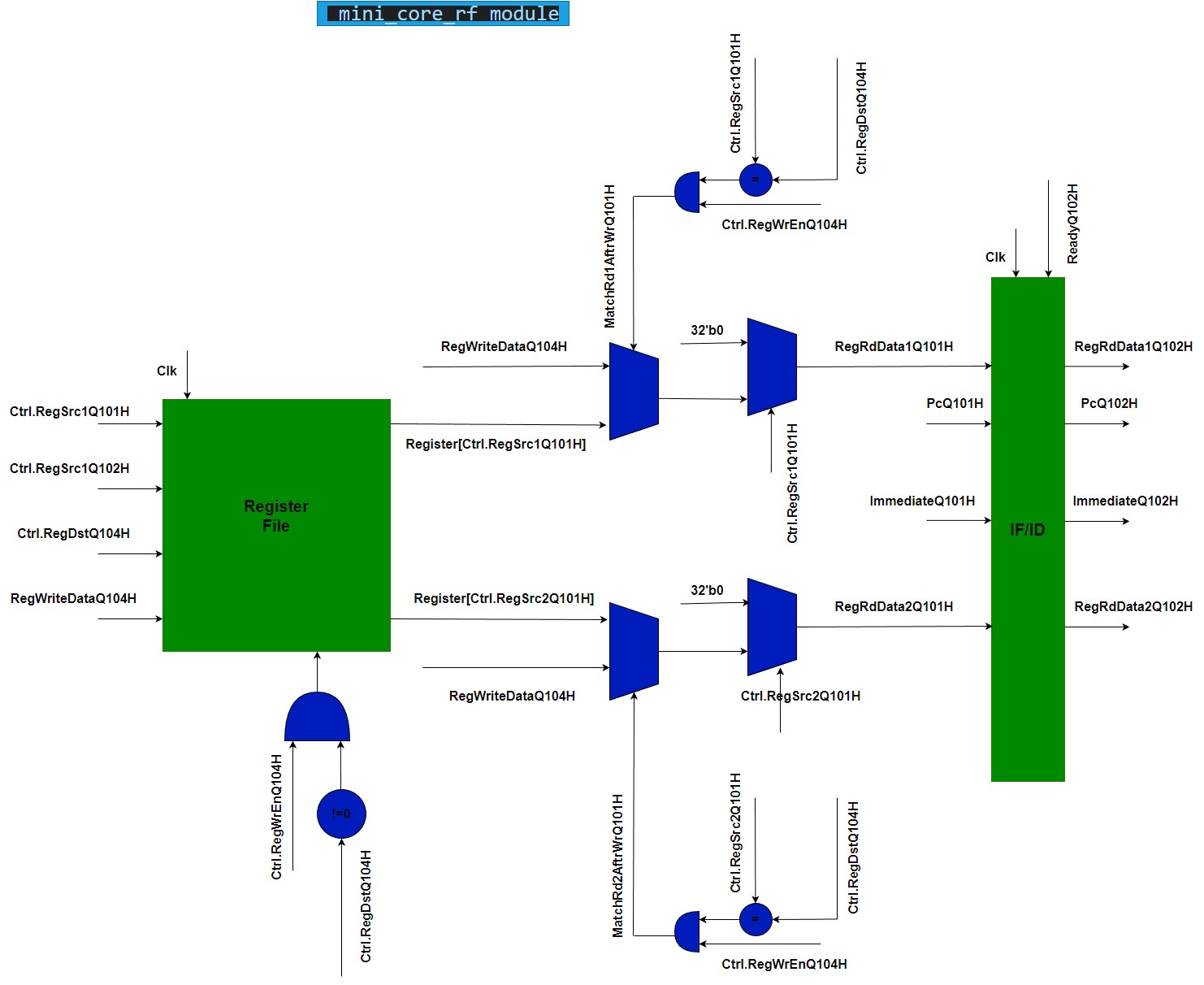
logic [RF_NUM_MSB:1][31:0] Register- Register file. We actually possess 31 registers rather than 32, as reg0 is consistently reserved as zero.logic MatchRd1AftrWrQ101H- This signal is used to determine whether the register read data 1 is the same as the register write data. If it is, then the register read data 1 is forwarded from the register write data.logic MatchRd2AftrWrQ101H- This signal is used to determine whether the register read data 2 is the same as the register write data. If it is, then the register- Other signals are self explanatory. You may use the figure below to understand the flow of data in the register file.
Forwarding in register file
Forwarding in register file occurs when the register read data at decode stage (Q101H) is the same as the register write data at WB stage (Q104H) meaning that the read data is not ready yet. In this case, we forward data from Q104H stage directly to Q101H stage. This is done by the following code: (example for register read data 1)
assign MatchRd1AftrWrQ101H = (Ctrl.RegSrc1Q101H == Ctrl.RegDstQ104H) && (Ctrl.RegWrEnQ104H);
assign RegRdData1Q101H = (Ctrl.RegSrc1Q101H == 5'b0) ? 32'b0                      : // Reading from Register[0] should result in '0
                         MatchRd1AftrWrQ101H         ? RegWrDataQ104H             : // forwards WrDataQ104H -> RdDataQ101H
                                                       Register[Ctrl.RegSrc1Q101H]; // Common Case - reading from Register file
This can happen for example in the following case:
add x1, x2, x3 (Q104H)
add x4, x5, x6 (Q103H)
add x7, x8, x9 (Q102H)
add x10, x1, x11 (Q101H)
We need data of x1 in Q101H stage, but it is not ready yet. So we forward the data from Q104H stage to Q101H stage.
mini_core_rf module abstract diagram
---------------------------------------------------------------------------------------------------------------------------------------
---------------------------------------------------------------------------------------------------------------------------------------
Please note that the above implementation behaves correctly but the real hardware implementation can be changed depending on the synthesis tool you use.